
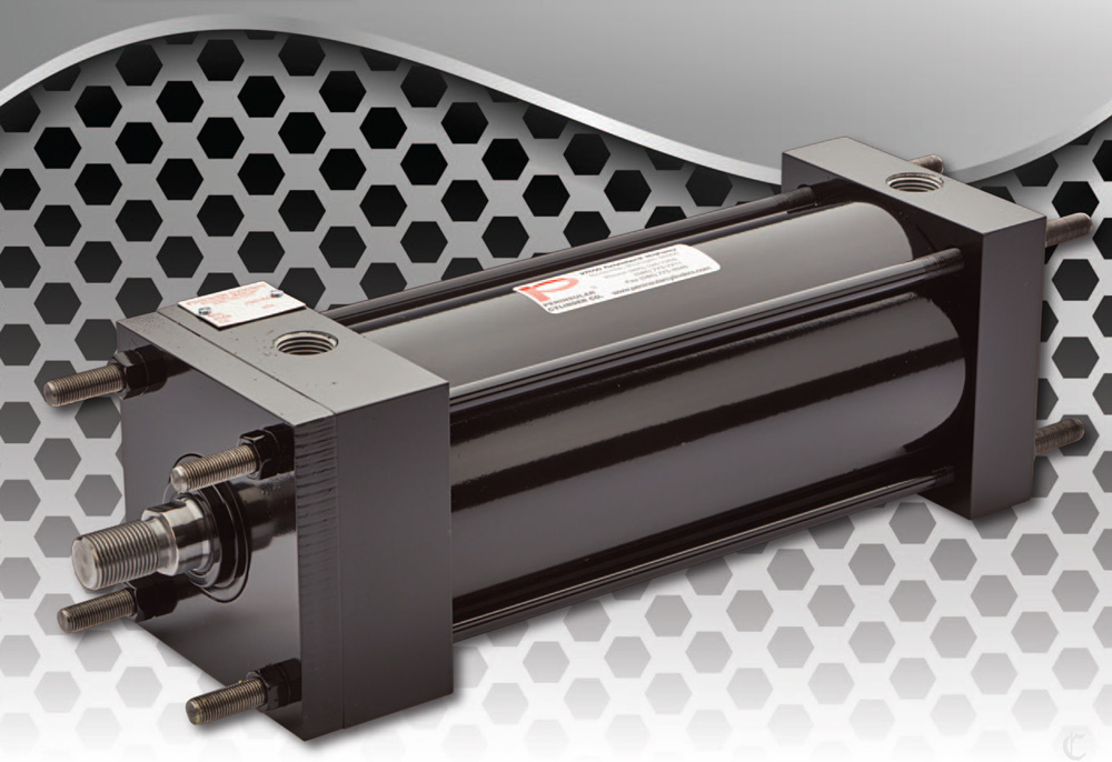

Peninsular Hydraulic Cylinder – LH Series
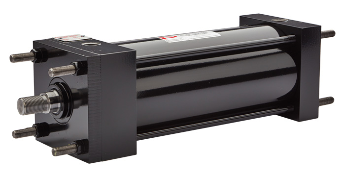
Steel Light & Medium Duty
1,500 PSI Working Pressure • 2,500 PSI Rated Pressure
NFPA Interchangeable
- Description
- Features & Benefits
Description
NFPA Pressure Rated (LH Series)
LH Series Product Facts
-
Hydraulic Model manufactured to NFPA standards
-
Up to 1500 PSI Working Pressure, Up to 2500 PSI Pressure Rated
-
Thicker wall tube than traditional low-pressure cylinders
-
Preloaded urethane blend poly seal
Value Added Options such as:
-
Hydraulic Polypak type seals
-
Piston wear bands
-
Rod wear bands
-
Rod Cartridge Drain Back System
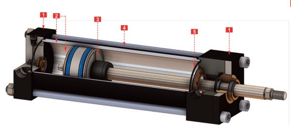
- Heads & Caps
Square, precision made carbon steel end covers. Precision machined for concentricity of tube, bearing, cushion and piston rod. Can be modified to accommodate proximity switches.
- Cylinder Tube
D.O.M. seamless 1020 to 1026 steel tube precision honed to 10/15 micro inch finish. Thicker wall tube than traditional low-pressure cylinders.
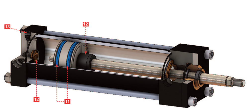
- Piston
One-piece fine grained ductile iron piston is threaded onto piston rod and held in place with thread locker. And a set screw to a secured position.
- Tie Rods
Larger diameter tie rods are used and made from 100,000 psi minimum yield, stress-proof, medium carbon steel with rolled threads at each end.
- Tube Seals
Nitrile axial placed O-Rings. Larger diameter tie rods, guards against extrusion of seal and hydraulic leaks under normal operating pressures.
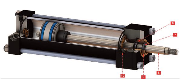
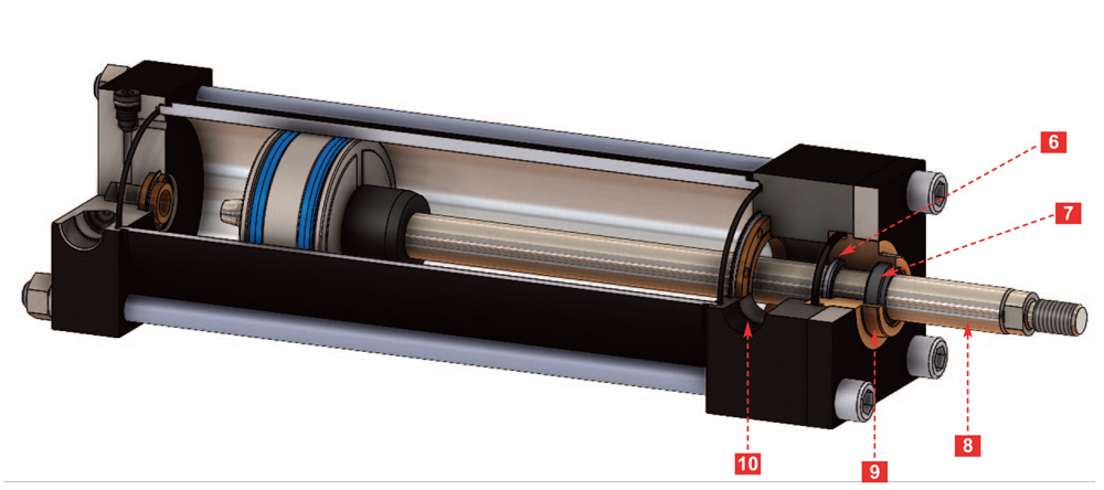
- Rod Seal
Beveled lip loaded U-cup 95A urethane X-Pac is positioned in a groove in the back end of the bearing cartridge ID. Pre-loaded seal provides positive static and dynamic sealing of piston rod at both high and low pressures.
- Rod Wiper
Urethane H type wiper guards against contaminants. Severe external conditions could require the addition of an optional metallic rod scraper installed ahead of the rod wiper to effectively provide dual protection from the elements. Prevents dust, dirt and grit from entering the bearing cartridge and cylinder, which significantly extends the cylinder life.
- Piston Rod
85,000 psi minimum yield strength chrome plated steel with core hardness of Rc 28-34. Rod is hard chrome-plated (.0003/.0005 thick) and polished to 12/15 micro inch finish. Solid male threads contain a radiused undercut. Resists wear and provides positive connections to existing machine components.
- Bearing Cartridge
Floating, self-aligning ductile iron retained by plate with cap screws; strong and shock resistant. A Buna-N O-Ring with back-up ring located around the cartridge OD prevents leakage around the outside of bearing cartridge and seal extrusion.
- Ports
NPT standard, SAE O-Ring optional. Metric & other thread size options.
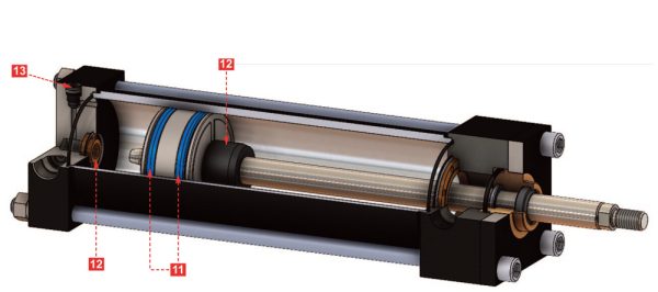
- Piston Seals
Asymmetrical Urethane U-Cups with seal material options available including backup rings. Step cut cast iron piston rings & high load piston seals are also available.
- Cushions
Floating Ductile iron, check type seal insert held in place by a retaining ring. Ductile iron rod end cushion hub is polished to 8/12 microinch finish RMS, and black oxided. Tapered leading edge assures proper entry into seal. Low friction break- away under lower hydraulic pressures are the result of an exclusive insert design. The seal “Step” which seats against the inside of the cylinder head provides maximum cushion effectiveness, thus assuring a longer cylinder life.
- Cushion Adjustment Screw
Steel needle valve with 90 durometer Nitrile O-Ring and backup ring. The captive adjustment screw can be locked in place and is flush with the end cap. The backup ring behind the O-Ring prevents fluid leakage around the adjustment screw, The cushion design allows fine adjustment of cushioning speed. Captive screw assures user safety.
- Optional Air Bleed System (Not Shown)
Manual air bleed plug is located on the cylinder tube.
- Optional Rod Drain Back System (Not Shown)
Drain feature is an additional groove cut into the front end of the bearing cartridge, between the rod wiper and rod seal, that drains off any accumulation of fluid between the seals. A cartridge drain port is located on the cartridge retainer plate for a user-installed drain line back to the reservoir. Captures hydraulic fluid and drains it back to the reservoir. This minimizes the slow weepage of hydraulic fluid through the rod wiper onto the piston rod. By capturing it and redirecting it to the tank